


A.P. LOCK
(Keyless Bushing)

A.P. Lock (Keyless Bushing) is a power transmission component that
enables to clamp shaft and hubs (i.e. pulley, gear etc.) simultaneously
through its surface pressure. S.I.M provides diverse options in regards
to size, body material and surface treatment.
SAPL-E Series

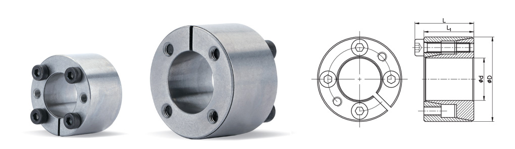
Dimensions / Performance
| Model d X D | CAD | Size (mm) | Max. Permissible Torque(Tc) (N·m) |
Max. Permissible Thrust Load(Pt) (kN) |
Surface Pressure (MPa) | Screw (Locking bolt) | Mass (g) | ||||
|---|---|---|---|---|---|---|---|---|---|---|---|
| L1 | L | Shaft(Pi) | Hub(Po) | Size | The no. of screws |
Fastening Torque(N·m) |
|||||
| SAPL-E-5 x 16 |  |
11 | 13.5 | 5 | 1.6 | 163 | 55 | M2.5x10 | 3 | 1.2 | 11 |
| SAPL-E-6 x 16 | |
11 | 13.5 | 6 | 2 | 150 | 55 | M2.5x10 | 3 | 1.2 | 12 |
| SAPL-E-8 x 18 | |
11 | 13.5 | 10 | 2.5 | 110 | 45 | M2.5x10 | 3 | 1.2 | 15 |
| SAPL-E-9 x 20 | |
13 | 15.5 | 15 | 3 | 110 | 45 | M2.5x10 | 4 | 1.2 | 20 |
| SAPL-E-10 x 20 | |
13 | 15.5 | 19 | 3.8 | 89 | 45 | M2.5x12 | 4 | 1.2 | 19 |
| SAPL-E-11 x 22 | |
13 | 15.5 | 21 | 3.8 | 81 | 41 | M2.5x12 | 4 | 1.2 | 24 |
| SAPL-E-12 x 22 | |
13 | 15.5 | 23 | 3.8 | 75 | 41 | M2.5x12 | 4 | 1.2 | 22 |
| SAPL-E-14 x 26 | |
17 | 20 | 39 | 5.5 | 71 | 38 | M3x16 | 4 | 2.1 | 39 |
| SAPL-E-15 x 28 | |
17 | 20 | 42 | 5.5 | 66 | 35 | M3x16 | 4 | 2.1 | 44 |
| SAPL-E-16 x 32 | |
17 | 21 | 77 | 9.6 | 107 | 54 | M4x16 | 4 | 4.9 | 68 |
| SAPL-E-17 x 35 | |
21 | 25 | 82 | 9.6 | 81 | 40 | M4x20 | 4 | 4.9 | 93 |
| SAPL-E-18 x 35 | |
21 | 25 | 87 | 9.6 | 77 | 40 | M4x20 | 4 | 4.9 | 90 |
| SAPL-E-19 x 35 | |
21 | 25 | 91 | 9.6 | 73 | 40 | M4x20 | 4 | 4.9 | 85 |
| SAPL-E-20 x 38 | |
21 | 26 | 157 | 15.7 | 113 | 60 | M5x20 | 4 | 10 | 120 |
| SAPL-E-22 x 40 | |
21 | 26 | 173 | 15.7 | 103 | 57 | M5x20 | 4 | 10 | 130 |
| SAPL-E-24 x 47 | |
26 | 32 | 268 | 22.3 | 110 | 56 | M6x24 | 4 | 17 | 220 |
| SAPL-E-25 x 47 | |
26 | 32 | 279 | 22.3 | 105 | 56 | M6x24 | 4 | 17 | 210 |
| SAPL-E-28 x 50 | |
26 | 32 | 468 | 33.5 | 141 | 79 | M6x24 | 6 | 17 | 240 |
| SAPL-E-30 x 55 | |
26 | 32 | 502 | 33.5 | 132 | 72 | M6x24 | 6 | 17 | 270 |
- Pt(Max. Permissible Thrust Load) indicates values at the zero(0) torque, and Tc(Max. Permissible Torque) at the zero(0) thrust load respectively. In case torque and thrust load occur simultaneously, please refer to the formula in the [Selection guide] page for combined load calculation.
- For the best performance, make sure all foreign substances e.g. corrosion, dust etc. are removed from each surface of shaft, hub, and A.P. Lock’s inner and outer ring.