Timing Pulley

Timing pulley is a part that transmits the rotational power
received from the timing belt to the shaft. Our products provide
sufficient tightening force without additional processing on shafts / pulleys, etc.
and support a variety of shaft fastening methods that are easy to install.

Additional Information about Clamping Methods

A.P. LOCK

Material

Steel

Please refer to “Dimensions / Performance” pages of SAPL-A Series (A.P.Lock)
in this catalogue for more details.

View More >

High Strength Aluminum Alloy

Please refer to “Dimensions / Performance” pages of SAPC Series (A.P.Lock)
in this catalogue for more details.

View More >
TAPER BUSHING
TAPER BUSHING – I TYPE

Size(mm)

Max. Permissible

Torque

(N·m)

Max. Permissible

Thrust Load

(kN)

Screw (Locking bolt)

d

D

D1

D2

d1

L

L1

Size

Fastening Torque (N·m)

6

22.5

16

8.5

3.3

10.5

3

5.6

1.87

M3x10

1.9

8

24.5

18

10.5

3.3

10.5

3

8.5

2.12

M3x10

1.9

10

29

21

12.75

4.4

13

4

18

3.59

M4x12

3.9

11

30

22

13.75

4.4

13

4

20

3.63

M4x12

3.9

12

31

23

14.75

4.4

13

4

23

3.76

M4x12

3.9

14

36

26

17.65

4.4

17

5

37

5.21

M4x18

3.9

15

37

27

18.65

4.4

17

5

39

5.1

M4x18

3.9

16

38

28

19.65

4.4

17

5

42

5.17

M4x18

3.9

17

39

29

20.65

4.4

17

5

45

5.23

M4x18

3.9

18

40

30

21.85

4.4

17

5

48

5.28

M4x18

3.9

19

42

32

22.85

4.4

17

5

49

5.12

M4x18

3.9

20

46

36

24.1

5.5

19

6

97

9.68

M5x18

7.8

22

47

37

25.75

5.5

19

6

110

9.98

M5x18

7.8

24

49

39

27.75

5.5

19

6

121

10

M5x18

7.8

25

51

41

28.75

5.5

19

6

124

9.9

M5x18

7.8

28

53

43

31.75

5.5

19

6

141

10

M5x18

7.8

30

56

46

33.75

5.5

19

6

149

9.89

M5x18

7.8

32

58

47

35.75

5.5

19

6

163

10.12

M5x18

7.8

35

61

50

39.1

5.5

20

6

173

9.88

M5x18

7.8

TAPER BUSHING (O Type)

Size(mm)

Max. Permissible

Torque

(N·m)

Max. Permissible

Thrust Load

(kN)

Screw (Locking bolt)

d

D

D1

D2

d1

L

L1

Size

Fastening Torque (N·m)

8

25.5

19

10

3.3

15.5

4

16

4

M3x12

2

10

30

22

12

4.5

16.5

5

39

5.34

M4x16

4

11

31

23

13

4.5

16.5

5

43

5.34

M4x16

4

12

32

24

14

4.5

16.5

5

48

5.34

M4x16

4

14

35

27

16.6

4.5

22

6

73

5.34

M4x18

4

15

36

28

17.6

4.5

22

6

78

5.34

M4x18

4

16

37

29

18.6

4.5

23

7

83

5.34

M4x18

4

17

38

30

19.6

4.5

23

7

88

5.34

M4x18

4

18

43

33

20.6

5.5

23

7

154

8.74

M5x20

8.3

19

45

35

22.4

5.5

23

7

163

8.74

M5x20

8.3

20

46

36

23.4

5.5

23

7

171

8.74

M5x20

8.3

22

48

38

24.6

5.5

23

7

186

8.74

M5x20

8.3

24

50

40

26.6

5.5

23

7

206

8.74

M5x20

8.3

25

52

42

28.4

5.5

23

7

216

8.74

M5x20

8.3

28

54

44

30.6

5.5

24

8

353

8.74

M5x25

8.3

30

57

47

33.4

5.5

24

8

382

8.74

M5x25

8.3

32

59

49

34.7

5.5

25

9

412

8.74

M5x25

8.3

35

63

53

38.4

5.5

26.5

9

451

8.74

M5x25

8.3

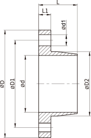
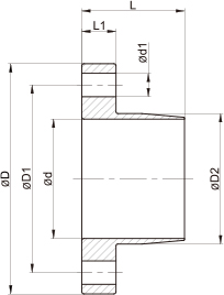
SIDE-CLAMP (Standard Keyway Information)
Shaft(Bore) Diameter Keyway Dimension Nominal Size
Ød b(mm) t(mm) (b x h)
Over ~ To Mark No Mark H J Size Tolerance
Size Tol.(E9) Tol.(H9) Tol.(Js9)
Ø6(over) ~ Ø8 2 +0.039
+0.014
+0.025
0
±0.0125 1 +0.1
0
2 x 2
Ø8 ~ Ø10 3 1.4 3 x 3
Ø10 ~ Ø12 4 +0.05
+0.02
+0.03
0
±0.015 1.8 4 x 4
Ø12 ~ Ø17 5 2.3 5 x 5
Ø17 ~ Ø22 6 2.8 6 x 6
Ø22 ~ Ø30 8 +0.061
+0.025
+0.036
0
±0.018 3.3 8 x 7
Ø30 ~ Ø38 10 +0.2
0
10 x 8
Ø38 ~ Ø44 12 +0.075
+0.032
+0.043
0
±0.0215 12 x 8
Ø44 ~ Ø50 14 3.8 14 x 9
Ø50 ~ Ø58 16 4.3 16 x 10
Ø58 ~ Ø65 18 4.4 18 x 11
Ø65 ~ Ø75 20 +0.092
+0.04
+0.052
0
±0.026 4.9 20 x 12
Ø75 ~ Ø85 22 5.4 22 x 14

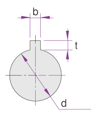
• The location of keyway on a coupling hub is determined by the standard product design of Sung-il Machinery. If you need a keyway in a different location, please discuss with our Customer Support team in advance.
• If you need to specify the length of keyway (axial direction) or tolerance for height and depth of keyway, please discuss with our Customer Support team in advance.
• Keyways can be processed on SC(Side-clamp) type only. (Not available on SPB, SPA types)