


Shaft Coupling

Coupling is a core component that transmits power and motion
from the driving shaft to the driven part while absorbing misalignment
and any possible factors that could reduce efficiency of machines
(e.g. vibration, noise, electric current, etc.)
SD Series Go to SD Series(Index)
Single Disk Type Coupling_High Strength Aluminum Alloy Body
- Product Overview
-
Dimensions / Performance / CAD
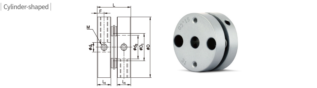
Side-clamp
Dimensions / Performance
| Model | CAD | Shape | Size (±0.3mm) | Screw | Permissible Torque (N·m) |
Max. rpm (min-1) |
Moment of Inertia (kg·m2) |
Static Torsional Stiffness (N·m/rad) |
Mass (g) |
Permissible Misalignment | ||||||||
|---|---|---|---|---|---|---|---|---|---|---|---|---|---|---|---|---|---|---|
| D | D1 | D2 | L | L1 | F | Size | Fastening Torque (N·m) |
Angular (˚) |
Parallel (mm) |
End- play (mm) |
||||||||
| SDS-16 | Cylinder | 16 | 6.7 | – | 12 | 5.1 | 2.5 | M2.5 | 0.5 | 0.6 | 16,000 | 1.8×10⁻⁷ | 270 | 5 | 0.5 | 0.02 | ±0.1 | |
| SDS-19 | 19 | 8.5 | – | 14.1 | 6.1 | 3 | M3 | 0.7 | 0.9 | 16,000 | 3.0×10⁻⁷ | 600 | 6 | 1 | 0.02 | ±0.1 | ||
| SDS-22 | 22.2 | 10 | – | 14.8 | 6.2 | 3 | M3 | 0.7 | 1.2 | 12,000 | 6.9×10⁻⁷ | 600 | 10 | 1 | 0.02 | ±0.1 | ||
| SDS-26 | 26.6 | 12.2 | – | 17.6 | 7.4 | 3.6 | M4 | 1.7 | 2.2 | 12,000 | 2.0×10⁻⁶ | 900 | 20 | 1 | 0.02 | ±0.15 | ||
| SDS-31 | 31.8 | 14.4 | – | 17.6 | 7.2 | 3.6 | M4 | 1.7 | 4 | 10,000 | 4.4×10⁻⁶ | 1,700 | 30 | 1 | 0.02 | ±0.2 | ||
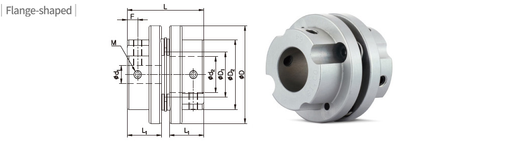
| SDS-42 | Flange /Cylinder |
42.5 | 18 | 29.3 / – | 30.8 / 31.4 | 13.4 / 13.7 | 4.6 / 6.5 | M4 | 1.7 | 8 | 8,000 | 1.7×10⁻⁵ | 2,800 | 65 | 1 | 0.02 | ±0.25 | |
| SDS-42(3) | 42.5 | 18 | 29.3 / – | 31.1 / 31.7 | 13.4 / 13.7 | 4.6 / 6.5 | M4 | 1.7 | 10 | 8,000 | 1.7×10⁻⁵ | 2,800 | 65 | 1 | 0.02 | ±0.25 | ||
| SDS-47 | 47 | 20.4 | 33 / – | 31.4 / 35.7 | 13.9 / 16 | 4.5 / 7.1 | M5 | 4 | 14 | 8,000 | 2.7×10⁻⁵ | 6,000 | 91 | 1 | 0.02 | ±0.25 | ||
| SDS-54 | 54 | 25 | 38.5 / – | 42.3 | 19 | 5.8 / 6.4 | M5 | 4 | 25 | 7,500 | 4.9×10⁻⁵ | 11,000 | 130 | 1 | 0.02 | ±0.25 | ||
| SDS-64 | 64 | 25.8 | 48 / – | 58.2 | 26 | 8 / 11 | M8 | 15 | 40 | 7,000 | 1.8×10⁻⁴ | 20,000 | 292 | 1 | 0.02 | ±0.25 | ||
- The Moment of Inertia and Mass values are based on products with max. Inner diameter.
- Permissible Torque is the value regarding to a coupling’s self-durability and is not related to slip-torque between the coupling bore and the shaft. (In general, the clamping force on set-screw type is weaker, therefore it is recommended that an additional keyway is processed for the enhanced clamping force.)
- If the same model has two different shapes (cylinder,flange), please indicate the cylinder type with the identification code ‘D’ after the inner diameter.
Standard Inner Diameter (ID)
| Model | Standard Inner Diameter (d1, d2) (mm) | ||||||||||||||||||||||||||||
|---|---|---|---|---|---|---|---|---|---|---|---|---|---|---|---|---|---|---|---|---|---|---|---|---|---|---|---|---|---|
| 3 | 4 | 4.5 | 5 | 6 | 6.35 | 7 | 8 | 9 | 9.525 | 10 | 11 | 12 | 12.7 | 14 | 15 | 15.875 | 16 | 17 | 18 | 19 | 20 | 21 | 22 | 24 | 25 | 26 | 28 | 30 | |
| SDS-16 | ● | ● | ● | ● | |||||||||||||||||||||||||
| SDS-19 | ● | ● | ● | ● | ● | ||||||||||||||||||||||||
| SDS-22 | ● | ● | ● | ● | ● | ● | ● | ● | ● | ●★ | |||||||||||||||||||
| SDS-26 | ● | ● | ● | ● | ● | ● | ● | ● | ● | ● | |||||||||||||||||||
| SDS-31 | ● | ● | ● | ● | ● | ● | ● | ● | ● | ● | ● | ●★ | ●★ | ||||||||||||||||
| SDS-42 | ● | ● | ● | ● | ● | ● | ● | ● | ● | ● | ● | ● | |||||||||||||||||
| SDS-47 | ● | ● | ● | ● | ● | ● | ● | ● | ● | ● | ● | ● | ● | ● | |||||||||||||||
| SDS-54 | ● | ● | ● | ● | ● | ● | ● | ● | ● | ● | ● | ● | |||||||||||||||||
| SDS-64 | ● | ● | ● | ● | ● | ● | ● | ● | ● | ● | ● | ● | ● | ●★ | ●★ | ●★ | ●★ | ||||||||||||
- The recommended shaft tolerance is h7.
- Custom process (e.g. non-standard Inner diameter, special tolerance etc.) is also available upon a special request in prior to order placement.
- Keyway is available. (Optional)
- Due to interference of the middle parts, make sure the shaft is only inserted into L1 depth for IDs with ★ mark. Consult us first if you’re concerned about misalignment.