


Shaft Coupling

Coupling is a core component that transmits power and motion
from the driving shaft to the driven part while absorbing misalignment
and any possible factors that could reduce efficiency of machines
(e.g. vibration, noise, electric current, etc.)
SD Series Go to SD Series(Index)
Double Disk Type Coupling_High Strength Aluminum Alloy Body
- Product Overview
-
Dimensions / Performance / CAD
Side-clamp – Cylinder-shaped
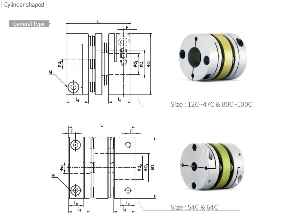
Dimensions / Performance (General Type)
| Model | CAD | Size (±0.3mm) | Screw | Permissible Torque (N·m) |
Max. rpm (min-1) |
Moment of Inertia (kg·m2) |
Static Torsional Stiffness (N·m/rad) |
Mass (g) |
Permissible Misalignment | Side- clamp Hub Split (W) |
||||||||
|---|---|---|---|---|---|---|---|---|---|---|---|---|---|---|---|---|---|---|
| D | D1 | L | L1 | L3 | F | Size | Fastening Torque (N·m) |
Angular (˚) |
Parallel (mm) |
End- play (mm) |
||||||||
| SDWA-12C | 12 | 5.5 | 15.7 | 5.9 | – | 1.9 | M1.6 | 0.25 | 0.2 | 14,000 | 7.5×10⁻⁸ | 85 | 4 | 1 | 0.03 | ±0.08 | X | |
| SDWA-16C | 16 | 6.3 | 21.2 | 7.8 | – | 2.5 | M2 | 0.5 | 0.6 | 14,000 | 3.3×10⁻⁷ | 200 | 9 | 1 | 0.05 | ±0.2 | X | |
| SDWB-16C | 16 | 6.3 | 23.2 | 7.8 | – | 2.5 | M2 | 0.5 | 0.6 | 14,000 | 3.7×10⁻⁷ | 200 | 10 | 1 | 0.05 | ±0.2 | X | |
| SDWA-19C | 19 | 8.4 | 23.3 | 8.7 | – | 2.9 | M2.6 | 1 | 0.9 | 14,000 | 7.4×10⁻⁷ | 300 | 14 | 1 | 0.05 | ±0.2 | X | |
| SDWB-19C | 19 | 8.4 | 26.3 | 8.7 | – | 2.9 | M2.6 | 1 | 0.9 | 14,000 | 7.9×10⁻⁷ | 300 | 15 | 1 | 0.05 | ±0.2 | X | |
| SDWA-22C | 22.2 | 9 | 25 | 8.7 | – | 2.8 | M2.6 | 1 | 1.2 | 10,000 | 1.3×10⁻⁶ | 400 | 18 | 1.5 | 0.12 | ±0.2 | X | |
| SDWB-22C | 22.2 | 9 | 27.2 | 8.7 | – | 2.8 | M2.6 | 1 | 1.2 | 10,000 | 1.4×10⁻⁶ | 400 | 19 | 1.5 | 0.12 | ±0.2 | X | |
| SDWA-26C | 26.6 | 12.2 | 32.5 | 10.6 | – | 3.4 | M3 | 1.7 | 2.2 | 10,000 | 3.4×10⁻⁶ | 600 | 34 | 1.5 | 0.15 | ±0.3 | X | |
| SDWA-31C | 31.8 | 14.4 | 33.5 | 11.6 | – | 3.7 | M3 | 1.7 | 4 | 9,000 | 7.5×10⁻⁶ | 1,300 | 52 | 1.5 | 0.15 | ±0.4 | X | |
| SDWB-31C | 31.8 | 14.4 | 38.5 | 11.6 | – | 3.7 | M3 | 1.7 | 4 | 9,000 | 8.8×10⁻⁶ | 1,300 | 60 | 1.5 | 0.15 | ±0.4 | X | |
| SDWA-35C | 35 | 16.2 | 34.6 | 12.7 | – | 4.4 | M4 | 3.5 | 5 | 8,500 | 1.2×10⁻⁵ | 1,500 | 67 | 1.5 | 0.16 | ±0.4 | X | |
| SDWC-35C | 35 | 16.2 | 38.1 | 12.7 | – | 4.4 | M4 | 3.5 | 5 | 8,500 | 1.4×10⁻⁵ | 1,500 | 75 | 1.5 | 0.16 | ±0.4 | X | |
| SDWA-39C | 39 | 17 | 39.5 | 13.7 | – | 4.3 | M4 | 3.5 | 6 | 8,000 | 2.1×10⁻⁵ | 1,800 | 95 | 1.5 | 0.18 | ±0.4 | X | |
| SDWA-39C(3) | 39 | 17 | 40.1 | 13.7 | – | 4.3 | M4 | 3.5 | 9 | 8,000 | 2.1×10⁻⁵ | 1,800 | 95 | 1.5 | 0.18 | ±0.4 | X | |
| SDWC-39C | 39 | 17 | 45 | 13.7 | – | 4.3 | M4 | 3.5 | 6 | 8,000 | 2.4×10⁻⁵ | 1,800 | 110 | 1.5 | 0.18 | ±0.4 | X | |
| SDWC-39C(3) | 39 | 17 | 45.6 | 13.7 | – | 4.3 | M4 | 3.5 | 9 | 8,000 | 2.4×10⁻⁵ | 1,800 | 110 | 1.5 | 0.18 | ±0.4 | X | |
| SDWC-42C | 42.5 | 18 | 46.2 | 13.7 | – | 4.3 | M4 | 3.5 | 8 | 8,000 | 3.3×10⁻⁵ | 2,000 | 120 | 1.5 | 0.18 | ±0.5 | X | |
| SDWC-42C(3) | 42.5 | 18 | 46.8 | 13.7 | – | 4.3 | M4 | 3.5 | 10 | 8,000 | 3.3×10⁻⁵ | 2,000 | 120 | 1.5 | 0.18 | ±0.5 | X | |
| SDWC-47C | 47 | 20.5 | 50 | 16 | – | 5.2 | M4 | 3.5 | 14 | 7,500 | 5.5×10⁻⁵ | 4,000 | 160 | 1.5 | 0.2 | ±0.5 | X | |
| SDWB-54C | 54 | 25 | 52.6 | 19 | 13 | 6.3 | M5 | 8 | 25 | 7,500 | 1.1×10⁻⁴ | 7,000 | 250 | 1.5 | 0.2 | ±0.5 | ○ | |
| SDWC-54C | 54 | 25 | 58.6 | 19 | 13 | 6.3 | M5 | 8 | 25 | 7,500 | 1.2×10⁻⁴ | 7,000 | 280 | 1.5 | 0.2 | ±0.5 | ○ | |
| SDWB-64C | 64 | 25.8 | 74.4 | 26 | 15.2 | 7.5 | M6 | 13 | 40 | 6,500 | 3.5×10⁻⁴ | 11,000 | 455 | 1.5 | 0.3 | ±0.5 | ○ | |
| SDWC-64C | 64 | 25.8 | 84.4 | 26 | 15.2 | 7.5 | M6 | 13 | 40 | 6,500 | 4.8×10⁻⁴ | 11,000 | 530 | 1.5 | 0.3 | ±0.5 | ○ | |
| SDW-80C | 80 | 35.8 | 81.8 | 29.7 | 19 | 9.4 | M8 | 30 | 85 | 6,000 | 8.1×10⁻⁴ | 20,000 | 860 | 2 | 0.4 | ±0.6 | ○ | |
| SDWC-80C | 80 | 35.8 | 98.3 | 29.7 | 19 | 9.4 | M8 | 30 | 85 | 6,000 | 9.7×10⁻⁴ | 20,000 | 1,020 | 2 | 0.5 | ±0.6 | ○ | |
| SDW-90C | 94.5 | 41.6 | 98.9 | 30.4 | 19 | 9.3 | M8 | 30 | 180 | 6,000 | 1.8×10⁻³ | 35,000 | 1,360 | 2 | 0.4 | ±0.8 | ○ | |
| SDW-100C | 104.5 | 47.7 | 103.8 | 30.7 | 19 | 9.3 | M8 | 30 | 250 | 6,000 | 2.9×10⁻³ | 50,000 | 1,700 | 2 | 0.4 | ±0.8 | ○ | |
- The Moment of Inertia and Mass values are based on products with max. Inner diameter.
- Permissible Torque is the value regarding to a coupling’s self-durability and is not related to slip-torque between the coupling bore and the shaft.
- Specially-designed split hubs are used for the size of 80C, 90C and 100C. (with 2 screws)
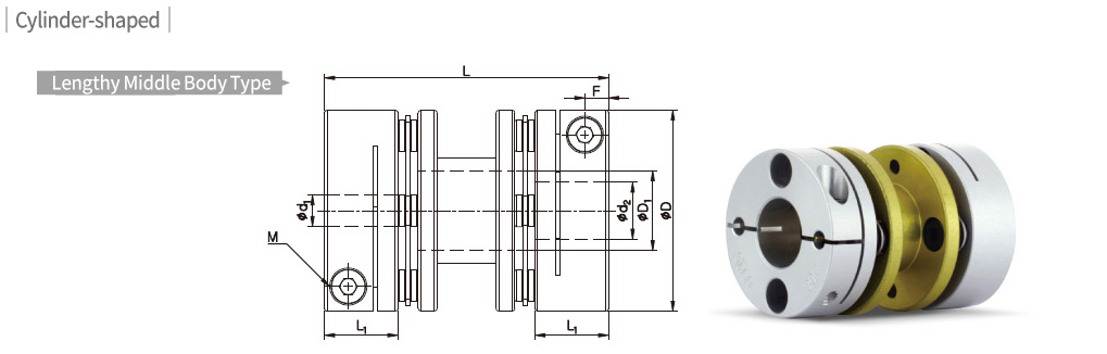
Dimensions / Performance (Lengthy Middle Body Type)
| Model | CAD | Size (±0.3mm) | Screw | Permissible Torque (N·m) |
Max. rpm (min-1) |
Moment of Inertia (kg·m2) |
Static Torsional Stiffness (N·m/rad) |
Mass (g) |
Permissible Misalignment | Side- clamp Hub Split (W) |
|||||||
|---|---|---|---|---|---|---|---|---|---|---|---|---|---|---|---|---|---|
| D | D1 | L | L1 | F | Size | Fastening Torque (N·m) |
Angular (˚) |
Parallel (mm) |
End- play (mm) |
||||||||
| SDA-22C | 22.2 | 8.3 | 33.2 | 8.7 | 2.8 | M2.6 | 1 | 1.2 | 10,000 | 1.5×10⁻⁶ | 400 | 20 | 1.5 | 0.12 | ±0.2 | X | |
| SDA-26C | 26.6 | 10.5 | 38.2 | 10.6 | 3.4 | M3 | 1.7 | 2.2 | 10,000 | 3.9×10⁻⁶ | 600 | 39 | 1.5 | 0.15 | ±0.3 | X | |
| SDA-31C | 31.8 | 12.7 | 44.9 | 11.6 | 3.7 | M3 | 1.7 | 4 | 9,000 | 8.8×10⁻⁶ | 1,300 | 60 | 1.5 | 0.15 | ±0.4 | X | |
| SDA-39C | 39 | 15.3 | 56.5 | 13.7 | 4.3 | M4 | 3.5 | 6 | 8,000 | 3.0×10⁻⁵ | 1,800 | 120 | 1.5 | 0.18 | ±0.4 | X | |
| SDA-39C(3) | 39 | 15.3 | 57.1 | 13.7 | 4.3 | M4 | 3.5 | 9 | 8,000 | 3.0×10⁻⁵ | 1,800 | 120 | 1.5 | 0.18 | ±0.4 | X | |
- The Moment of Inertia and Mass values are based on products with max. Inner diameter.
- Non-standard lengthy middle body type can be customized.
- Permissible Torque is the value regarding to a coupling’s self-durability and is not related to slip-torque between the coupling bore and the shaft.
Standard Inner Diameter (12C ~ 47C)
| Model | Standard Inner Diameter (d1, d2) (mm) | |||||||||||||||||||||
|---|---|---|---|---|---|---|---|---|---|---|---|---|---|---|---|---|---|---|---|---|---|---|
| 3 | 4 | 4.5 | 5 | 6 | 6.35 | 7 | 8 | 9 | 9.525 | 10 | 11 | 12 | 12.7 | 14 | 15 | 15.875 | 16 | 17 | 18 | 19 | 20 | |
| SD□□-12C | ● | ● | ●★ | |||||||||||||||||||
| SD□□-16C | ● | ● | ● | ● | ||||||||||||||||||
| SD□□-19C | ● | ● | ● | ● | ● | |||||||||||||||||
| SD□□-22C | ● | ● | ● | ● | ● | ● | ● | ● | ●★ | ●★ | ||||||||||||
| SD□□-26C | ● | ● | ● | ● | ● | ● | ● | ● | ● | ● | ||||||||||||
| SD□□-31C | ● | ● | ● | ● | ● | ● | ● | ● | ● | ● | ● | ●★ | ●★ | |||||||||
| SD□□-35C | ● | ● | ● | ● | ● | ● | ● | ● | ● | ● | ● | ● | ● | ●★ | ●★ | |||||||
| SD□□-39C | ● | ● | ● | ● | ● | ● | ● | ● | ● | ● | ● | ● | ● | ● | ● | |||||||
| SD□□-42C | ● | ● | ● | ● | ● | ● | ● | ● | ● | ● | ● | ● | ● | ● | ● | ●★ | ●★ | |||||
| SD□□-47C | ● | ● | ● | ● | ● | ● | ● | ● | ● | ● | ● | ● | ● | ● | ●★ | |||||||
Standard Inner Diameter (ID) (54C ~ 100C)
| Model | Standard Inner Diameter (d1, d2) (mm) | ||||||||||||||||||||||
|---|---|---|---|---|---|---|---|---|---|---|---|---|---|---|---|---|---|---|---|---|---|---|---|
| 10 | 11 | 12 | 12.7 | 14 | 15 | 15.875 | 16 | 17 | 18 | 19 | 20 | 22 | 24 | 25 | 26 | 28 | 30 | 32 | 35 | 40 | 45 | 50 | |
| SD□□-54C | ● | ● | ● | ● | ● | ● | ● | ● | ● | ● | ● | ● | ● | ● | ●★ | ||||||||
| SD□□-64C | ● | ● | ● | ● | ● | ● | ● | ● | ● | ● | ● | ● | ●★ | ●★ | ●★ | ●★ | ●★ | ||||||
| SD□□-80C | ● | ● | ● | ● | ● | ● | ● | ● | ● | ● | ● | ● | ● | ● | ●★ | ||||||||
| SD□□-90C | ● | ● | ● | ● | ● | ● | ● | ● | ● | ● | ●★ | ||||||||||||
| SD□□-100C | ● | ● | ● | ● | ● | ● | ● | ● | ● | ● | ● | ●★ | |||||||||||
- The recommended shaft tolerance is h7.
- Custom process (e.g. non-standard Inner diameter, special tolerance etc.) is also available upon a special request in prior to order placement. – ※ Exception Item: SDWA-12C
- Keyway is available. (Optional)
- Due to interference of the middle parts, make sure the shaft is only inserted into L1 depth for IDs with ★ mark. Consult us first if you’re concerned about misalignment.
- Side-clamp Hub Split is available (Optional)
Slip Torque
- The below table shows the actual permissible torque values when the slip torque value is lower than the coupling’s permissible torque value.
- If the slip torque value is lower than the coupling’s permissible torque value, please check and compare between the slip torque in the below table and the operating torque value of the connected motor. It is safer to size up the coupling or use a key/keyway when the slip torque value is lower than the motor’s operating torque.
- The below slip torque values may be subject to change according to different testing conditions. (e.g. shaft tolerance, surface roughness, surface treatment or acceleration/deceleration of driving shafts). On the other hand, the values could be affected when a different kind of fastening screw is used (body material or surface treatment). Therefore, we recommend you test under the same conditions before mounting.
| Model | Permissible Torque(N·m) |
Slip Torque (N·m) by Inner Diameter (d1, d2) | |||||||||||||||||
|---|---|---|---|---|---|---|---|---|---|---|---|---|---|---|---|---|---|---|---|
| 3 | 4 | 4.5 | 5 | 6 | 6.35 | 7 | 8 | 9 | 9.525 | 10 | 11 | 12 | 12.7 | 14 | 15 | 15.875 | 16 | ||
| SD□□-16C | 0.6 | 0.6 | |||||||||||||||||
| SD□□-19C | 0.9 | ||||||||||||||||||
| SD□□-22C | 1.2 | 1.1 | |||||||||||||||||
| SD□□-26C | 2.2 | 2 | 2 | ||||||||||||||||
| SD□□-31C | 4 | 3 | |||||||||||||||||
| SD□□-35C | 5 | 5 | |||||||||||||||||
| SD□□-39C | 6 | 5.5 | 6 | 6.5 | 7 | 9 | |||||||||||||
| SD□□-39C(3) | 9 | ||||||||||||||||||
| SD□□-42C | 8 | 4.5 | 6 | 8 | 10 | ||||||||||||||
| SD□□-42C(3) | 10 | ||||||||||||||||||
| SD□□-47C | 14 | 10 | 11 | 12 | |||||||||||||||
| Model | Permissible Torque(N·m) |
Slip Torque (N·m) by Inner Diameter (d1, d2) | |||||||||||||||||||
|---|---|---|---|---|---|---|---|---|---|---|---|---|---|---|---|---|---|---|---|---|---|
| 10 | 11 | 12 | 12.7 | 14 | 15 | 16 | 18 | 19 | 20 | 22 | 24 | 25 | 28 | 30 | 32 | 35 | 40 | 45 | 50 | ||
| SD□□-54C | 25 | ||||||||||||||||||||
| SD□□-64C | 40 | ||||||||||||||||||||
| SD□□-80C | 85 | ||||||||||||||||||||
| SD□□-90C | 180 | 100 | 110 | 130 | 150 | ||||||||||||||||
| SD□□-100C | 250 | 136 | 140 | 144 | 152 | 180 | 185 | 192 | 216 | 230 | 240 | 250 | |||||||||
Side-clamp – Flange-shaped (Low-inertia)
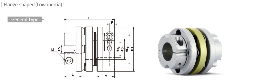
Dimensions / Performance (General Type)
| Model | CAD | Size (±0.3mm) | Screw | Permissible Torque (N·m) |
Max. rpm (min-1) |
Moment of Inertia (kg·m2) |
Static Torsional Stiffness (N·m/rad) |
Mass (g) |
Permissible Misalignment | ||||||||
|---|---|---|---|---|---|---|---|---|---|---|---|---|---|---|---|---|---|
| D | D1 | D2 | L | L1 | F | Size | Fastening Torque (N·m) |
Angular (˚) |
Parallel (mm) |
End- play (mm) |
|||||||
| SDWB-35C | 35 | 16.2 | 21.5 | 34.6 | 12.7 | 3.9 | M3 | 1.7 | 5 | 8,500 | 6.1×10⁻⁶ | 1,500 | 44 | 1.5 | 0.16 | ±0.4 | |
| SDWD-35C | 35 | 16.2 | 21.5 | 38.1 | 12.7 | 3.9 | M3 | 1.7 | 5 | 8,500 | 8.2×10⁻⁶ | 1,500 | 55 | 1.5 | 0.16 | ±0.4 | |
| SDWA-42C | 42.5 | 18 | 29.3 | 39.7 | 13.4 | 3.8 | M3 | 1.7 | 8 | 8,000 | 2.1×10⁻⁵ | 2,000 | 84 | 1.5 | 0.18 | ±0.5 | |
| SDWA-42C(3) | 42.5 | 18 | 29.3 | 40.3 | 13.4 | 3.8 | M3 | 1.7 | 10 | 8,000 | 2.1×10⁻⁵ | 2,000 | 84 | 1.5 | 0.18 | ±0.5 | |
| SDWB-42C | 42.5 | 18 | 29.3 | 44.2 | 13.4 | 3.8 | M3 | 1.7 | 8 | 8,000 | 2.4×10⁻⁵ | 2,000 | 94 | 1.5 | 0.18 | ±0.5 | |
| SDWB-42C(3) | 42.5 | 18 | 29.3 | 44.8 | 13.4 | 3.8 | M3 | 1.7 | 10 | 8,000 | 2.4×10⁻⁵ | 2,000 | 94 | 1.5 | 0.18 | ±0.5 | |
| SDWA-47C | 47 | 20.5 | 33/*38 | 45.6 | 16.7 | 5 | M4 | 3.5 | 14 | 7,500 | 3.6×10⁻⁵ | 4,000 | 120 | 1.5 | 0.2 | ±0.5 | |
| SDWB-47C | 47 | 20.5 | 33/*38 | 51.4 | 16.7 | 5 | M4 | 3.5 | 14 | 7,500 | 3.9×10⁻⁵ | 4,000 | 132 | 1.5 | 0.2 | ±0.5 | |
| SDWA-54C | 54 | 25 | 38.5 | 60.6 | 21.4 | 6.1 | M5 | 8 | 25 | 7,500 | 7.2×10⁻⁵ | 7,000 | 192 | 1.5 | 0.2 | ±0.5 | |
| SDWA-64C | 64 | 25.8 | 48 | 74.4 | 26 | 7.5 | M6 | 13 | 40 | 6,500 | 2.2×10⁻⁴ | 11,000 | 373 | 1.5 | 0.3 | ±0.5 | |
- The Moment of Inertia and Mass values are based on products with max. Inner diameter.
- Permissible Torque is the value regarding to a coupling’s self-durability and is not related to slip-torque between the coupling bore and the shaft.
- Please refer to * marked value for D2 of OD 47 products when ID is over 18mm.
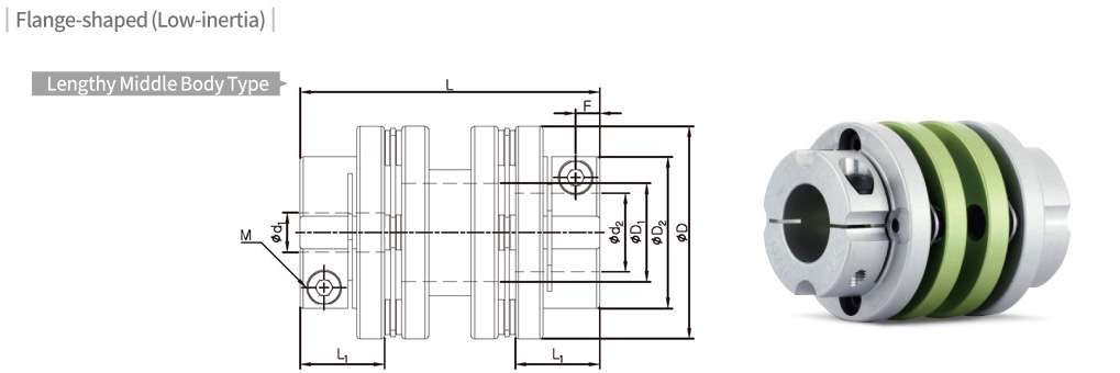
Dimensions / Performance (Lengthy Middle Body Type)
| Model | CAD | Size (±0.3mm) | Screw | Permissible Torque (N·m) |
Max. rpm (min-1) |
Moment of Inertia (kg·m2) |
Static Torsional Stiffness (N·m/rad) |
Mass (g) |
Permissible Misalignment | ||||||||
|---|---|---|---|---|---|---|---|---|---|---|---|---|---|---|---|---|---|
| D | D1 | D2 | L | L1 | F | Size | Fastening Torque (N·m) |
Angular (˚) |
Parallel (mm) |
End- play (mm) |
|||||||
| SDAA-42C | 42.5 | 18 | 29.3 | 50 | 13.4 | 3.8 | M3 | 1.7 | 8 | 8,000 | 2.7×10⁻⁵ | 2,000 | 105 | 1.5 | 0.18 | ±0.5 | |
| SDAA-42C(3) | 42.5 | 18 | 29.3 | 50.6 | 13.4 | 3.8 | M3 | 1.7 | 10 | 8,000 | 2.7×10⁻⁵ | 2,000 | 105 | 1.5 | 0.18 | ±0.5 | |
| SDAB-42C | 42.5 | 18 | 29.3 | 57.9 | 13.4 | 3.8 | M3 | 1.7 | 8 | 8,000 | 2.8×10⁻⁵ | 2,000 | 110 | 1.5 | 0.18 | ±0.5 | |
| SDAB-42C(3) | 42.5 | 18 | 29.3 | 58.5 | 13.4 | 3.8 | M3 | 1.7 | 10 | 8,000 | 2.8×10⁻⁵ | 2,000 | 110 | 1.5 | 0.18 | ±0.5 | |
| SDAC-42C | 42.5 | 18 | 29.3 | 67.3 | 13.4 | 3.8 | M3 | 1.7 | 8 | 8,000 | 2.9×10⁻⁵ | 2,000 | 115 | 1.5 | 0.18 | ±0.5 | |
| SDAC-42C(3) | 42.5 | 18 | 29.3 | 67.9 | 13.4 | 3.8 | M3 | 1.7 | 10 | 8,000 | 2.9×10⁻⁵ | 2,000 | 115 | 1.5 | 0.18 | ±0.5 | |
| SDAA-47C | 47 | 20 | 33/*38 | 63.8 | 16.7 | 5 | M4 | 3.5 | 14 | 7,500 | 4.5×10⁻⁵ | 4,000 | 152 | 1.5 | 0.2 | ±0.5 | |
| SDAB-47C | 47 | 20 | 33/*38 | 90.7 | 16.7 | 5 | M4 | 3.5 | 14 | 7,500 | 5.1×10⁻⁵ | 4,000 | 172 | 1.5 | 0.2 | ±0.5 | |
| SDAA-54C | 54 | 24.3 | 38.5 | 76 | 21.4 | 6.1 | M5 | 8 | 25 | 7,500 | 9.0×10⁻⁵ | 7,000 | 240 | 1.5 | 0.2 | ±0.5 | |
| SDAB-54C | 54 | 24.3 | 38.5 | 89.9 | 21.4 | 6.1 | M5 | 8 | 25 | 7,500 | 1.1×10⁻⁴ | 7,000 | 266 | 1.5 | 0.2 | ±0.5 | |
| SDA-64C | 64 | 25.8 | 48 | 89.9 | 26 | 7.5 | M6 | 13 | 40 | 6,500 | 2.7×10⁻⁴ | 11,000 | 450 | 1.5 | 0.3 | ±0.5 | |
- The Moment of Inertia and Mass values are based on products with max. Inner diameter.
- Non-standard lengthy middle body type can be customized.
- Permissible Torque is the value regarding to a coupling’s self-durability and is not related to slip-torque between the coupling bore and the shaft.
- Please refer to * marked value for D2 of OD 47 products when ID is over 18mm.
Standard Inner Diameter (ID)
| Model | Standard Inner Diameter (d1, d2) (mm) | |||||||||||||||||||||
|---|---|---|---|---|---|---|---|---|---|---|---|---|---|---|---|---|---|---|---|---|---|---|
| 5 | 6 | 6.35 | 7 | 8 | 9 | 9.525 | 10 | 11 | 12 | 12.7 | 14 | 15 | 15.875 | 16 | 17 | 18 | 19 | 20 | 22 | 24 | 25 | |
| SD□□-35C | ● | ● | ● | ● | ● | ● | ● | ● | ||||||||||||||
| SD□□-42C | ● | ● | ● | ● | ● | ● | ● | ● | ● | ● | ● | ● | ||||||||||
| SD□□-47C | ● | ● | ● | ● | ● | ● | ● | ● | ● | ● | ● | ● | ● | ● | ||||||||
| SD□□-54C | ● | ● | ● | ● | ● | ● | ● | ● | ● | ● | ● | ● | ||||||||||
| SD□□-64C | ● | ● | ● | ● | ● | ● | ● | ● | ● | ● | ● | ● | ●★ | |||||||||
- The recommended shaft tolerance is h7.
- Custom process (e.g. non-standard Inner diameter, special tolerance etc.) is also available upon a special request in prior to order placement.
- Keyway is available. (Optional)
- Due to interference of the middle parts, make sure the shaft is only inserted into L1 depth for IDs with ★ mark. Consult us first if you’re concerned about misalignment.
Slip Torque
- The below table shows the actual permissible torque values when the slip torque value is lower than the coupling’s permissible torque value.
- If the slip torque value is lower than the coupling’s permissible torque value, please check and compare between the slip torque in the below table and the operating torque value of the connected motor. It is safer to size up the coupling or use a key/keyway when the slip torque value is lower than the motor’s operational torque.
- The below slip torque values may be subject to change according to different testing conditions. (e.g. shaft tolerance, surface roughness, surface treatment or acceleration/deceleration of driving shafts). On the other hand, the values could be affected when a different kind of fastening screw is used (body material or surface treatment). Therefore, we recommend you test under the same conditions before mounting.
| Model | Permissible Torque (N·m) |
Slip Torque (N·m) by Inner Diameter (d1, d2) | |||||||||||||||||||
|---|---|---|---|---|---|---|---|---|---|---|---|---|---|---|---|---|---|---|---|---|---|
| 5 | 6 | 6.35 | 7 | 8 | 9 | 9.525 | 10 | 11 | 12 | 12.7 | 14 | 15 | 15.875 | 16 | 17 | 18 | 19 | 20 | 21 | ||
| SD□□-35C | 5 | 3.2 | 3.5 | 3.8 | |||||||||||||||||
| SD□□-42C | 8 | 3 | 3 | 3.5 | 4 | 6 | 7 | 9 | 9.5 | 10 | |||||||||||
| SD□□-42C(3) | 10 | ||||||||||||||||||||
| SD□□-47C | 14 | 10 | 11 | 12 | 14 | ||||||||||||||||
| SD□□-54C | 25 | ||||||||||||||||||||
| SD□□-64C | 40 | 36 | 37 | ||||||||||||||||||