


Support Unit For Ball screw

Support unit for ball screw helps to support each shaft-ends of
ball screw. We, S.I.M provides diverse options according to sizes,
loads and purposes for our customers’ best convenience.
Support Unit for Ball Screw (Index)
Support Unit (Grease injection)

- Product Overview
-
Specification
Structure
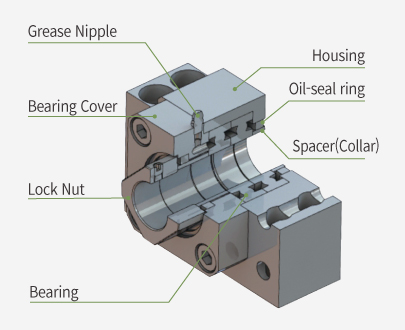
- Advance design with a nipple being attached and a passage carved on the bearing cover for a easier grease refill
- Prevention of foreign material and leak of grease by the inner oil-seal rings
- Accompanied by a high accuracy lock-nut and collars(spacer)
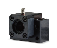
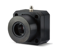
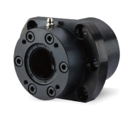
Features of BK-G, FK-G & SWBK-G Series
- Easy and Simple Grease Injection : This structure does not require the mounted Support unit to be detached from the ball screw and grease can be simply injected through the nipple on the body.
- Enhanced Lubrication Performance & Reduced Bearing Friction : In terms that it is possible to frequently refill grease, it helps to reduce friction/abrasion of bearing and eventually extends the lifespan.
- When a Support unit is mounted at a volatile circumstance or used with vertical drive motors, grease usually gets disappeared and lubrication of bearing doesn’t run smoothly. Thus, this Grease injection-type Support Unit series lets you refill grease easily and solves this issue.
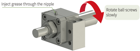
How To Inject(Refill) Grease
- With the support unit installed, slowly rotate the ball screw and gradually inject grease through the grease nipple.
- Please refer to the table below for the recommended amount of grease to be injected.
- Adjust the actual injection amount according to the operating conditions and grease injection cycle of the equipment.
- Be cautious not to inject grease rapidly or in excessive quantities, as it may cause the oil seal to dislocate from its proper position.
Recommended Amount of Grease
| Bearing Model |
Support Unit Model |
Recommended amount of grease (g) | ||
|---|---|---|---|---|
| Double-row(DF/DB) | Triple-row(DFD) | Four-row(DFF) | ||
| 7203AW | BK-17-G | 4 | – | – |
| FK-17-G | ||||
| 7004AW | BK-20-G | 4 | – | – |
| 7204AW | FK-20-G | 4 | – | – |
| 7205AW | BK-25-G | 4 | – | – |
| FK-25-G | ||||
| 7206AW | BK-30-G | 6 | – | – |
| FK-30-G | ||||
| 7208AW | BK-40-G | 8 | – | – |
| FK-40-G | ||||
| 17TAC 47C | SWBK-17-G | 4 | 6 | – |
| 20TAC 47C | SWBK-20-G | 4 | 6 | – |
| 25TAC 62C | SWBK-25-G | 4 | 6 | – |
| 30TAC 62C | SWBK-30-G | 4 | 6 | – |
| 35TAC 72C | SWBK-35-G | 4 | 6 | 8 |
| 40TAC 72C | SWBK-40-G | 4 | 6 | 8 |
| 50TAC 100C | SWBK-50-G | 4 | 6 | 8 |
How to Order
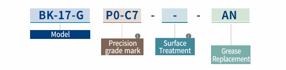
| ① Precision Grade Mark |
Mark | Bearing Precision Grade | Preload |
|---|---|---|---|
| P5 | P5 | Medium | |
| C8 | General | Medium | |
| P0-C7 | General | Light |
| ② Surface Treatment |
Mark | Surface Treatment |
|---|---|---|
| No mark | Black Oxide | |
| RA | Low temperature Black Chrome Plating (Raydent) |
| Grease Model | Standard | LG2 | AFE-CA | AFF | HT-Z1 | NBU-15 | XL-600 |
|---|---|---|---|---|---|---|---|
| Mark | No mark | AG | AE | AF | AH | AN | AX |
※ For detailed information regarding grease replacement, please refer to the guideline pages in the catalogue under the “Made-To-Order Process.”
List of bearings
| Bearing Inner dia. (mm) |
Model | Bearing | |||||
|---|---|---|---|---|---|---|---|
| BK-G | FK-G | SWBK-G | P5 | C8 | P0-C7 | TAC(SWBK-G) | |
| 17 | BK-17-G | FK-17-G | SWBK-17-G | 7203ATYNDFMP5 | 7203AWDFM | 7203AW | 17TAC 47C |
| 20 | FK-20-G | SWBK20-G | 7204ATYNDFMP5 | 7204AWDFM | 7204AW | 20TAC 47C | |
| BK-20-G | 7004ATYNDFMP5 | 7004AWDFM | 7004AW | ||||
| 25 | BK-25-G | FK-25-G | SWBK-25-G | 7205ATYNDFMP5 | 7205AWDFM | 7205AW | 25TAC 62C |
| 30 | BK-30-G | FK-30-G | SWBK-30-G | 7206ATYNDFMP5 | 7206AWDFM | 7206AW | 30TAC 62C |
| 35 | BK-35-G | FK-35-G | SWBK-35-G | 7207ATYNDFMP5 | 7207AWDFM | 7207AW | 35TAC 72C |
| 40 | BK-40-G | FK-40-G | SWBK-40-G | 7208ATYNDFMP5 | 7208AWDFM | 7208AW | 40TAC 72C |
Recommended Shape of Ball Screw Shaft-End (Fixed Side / General Load)
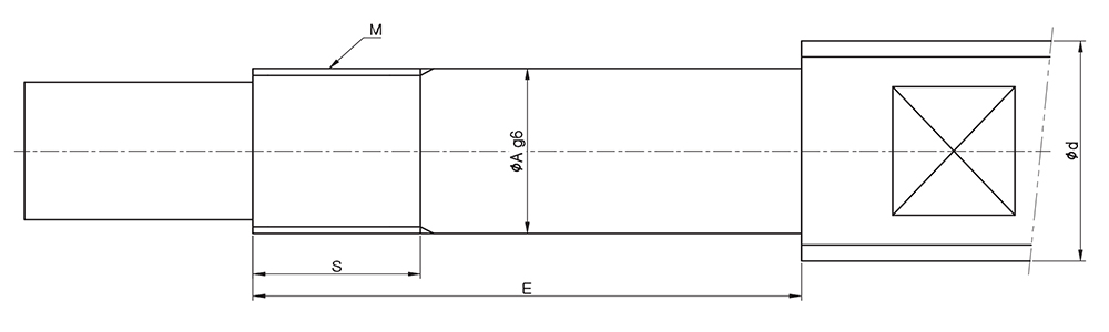
| Demensions(mm) | Lock-nut | ||||||||
|---|---|---|---|---|---|---|---|---|---|
| d | A | BK | FK | Model | Size M x pitch |
||||
| Model | E | S | Model | F | S | ||||
| Ø25 – Ø28 | 17 | BK-17-G | 65 | 17 | FK-17-G | 67 | 17 | RN-17 | M17 x 1.0 |
| 20 | BK-20-G | 65 | 17 | FK-20-G | 73 | 17 | RN-20 | M20 x 1.0 | |
| Ø30 – Ø36 | 25 | BK-25-G | 80 | 20 | FK-25-G | 86 | 20 | RN-25 | M25 x 1.5 |
| Ø40 | 30 | BK-30-G | 87 | 25 | FK-30-G | 87 | 25 | RN-30 | M30 x 1.5 |
| Ø45 | 35 | BK-35-G | 93 | 28 | FK-35-G | 93 | 28 | RN-35 | M35 x 1.5 |
| Ø50 – Ø55 | 40 | BK-40-G | 114 | 35 | FK-40-G | 114 | 35 | RN-40 | M40 x 1.5 |
Recommended Shape of Ball Screw Shaft-End (Fixed Side / High Load)
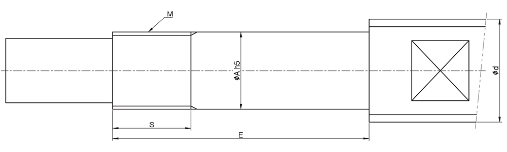
| Dimensions(mm) | Lock-nut | ||||||
|---|---|---|---|---|---|---|---|
| d | A | SWBK | Model | Size M x pitch |
|||
| Model | E | S | |||||
| Ø25 – Ø28 | 17 | SWBK-17-G | DF | 93 | 23 | HLRN-17 | M17 x 1.0 |
| DFD | 108 | ||||||
| 20 | SWBK-20-G | DF | 93 | 23 | HLRN-20 | M20 x 1.0 | |
| DFD | 108 | ||||||
| Ø30 – Ø36 | 25 | SWBK-25-G | DF | 98 | 26 | HLRN-25 | M25 x 1.5 |
| DFD | 113 | ||||||
| Ø40 | 30 | SWBK-30-G | DF | 98 | 26 | HLRN-30 | M30 x 1.5 |
| DFD | 113 | ||||||
| Ø45 | 35 | SWBK-35-G | DF | 101 | 28 | HLRN-35 | M35 x 1.5 |
| DFD | 116 | ||||||
| DFF | 131 | ||||||
| Ø50 – Ø55 | 40 | SWBK-40-G | DF | 106 | 30 | HLRN-40 | M40 x 1.5 |
| DFD | 121 | ||||||
| DFF | 136 | ||||||
| Ø63 – Ø70 | 50 | SWBK-50-G | DF | 124 | 34 | HLRN-50 | M50 x 1.5 |
| DFD | 144 | ||||||
| DFF | 164 | ||||||