


Timing Pulley

Timing pulley is a part that transmits the rotational power
received from the timing belt to the shaft. Our products provide
sufficient tightening force without additional processing on shafts / pulleys, etc.
and support a variety of shaft fastening methods that are easy to install.
SATP-8YU Series 
Timing Pulley (High Strength Aluminum Alloy) 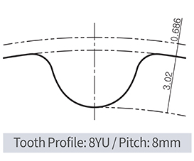 + A.P.LOCK (Steel) Mounted Type
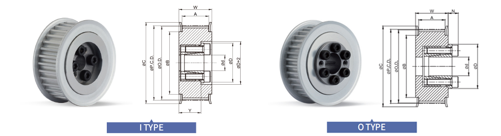
Dimensions / Performance
|
TYPE |
CAD |
NT |
P.C.D. |
O.D. |
C |
B |
ID Range (I type) |
ID Range (O type) |
|||
|
BW200 (A:21.7, W:28) |
BW250 (A:26.7, W33) |
BW150 (A:16.7, W:23) |
BW200 (A:21.7, W:28) |
BW250 (A:26.7, W:33) |
|||||||
|
SATP-8YU SPAS
|
20 |
50.93 |
49.56 |
62 |
40 |
12, 14 |
12, 14 |
12, 14 |
12, 14 |
12, 14 |
|
|
22 |
56.02 |
54.65 |
64 |
45 |
12 ~ 16 |
12 ~ 16 |
12 ~ 16 |
12 ~ 16 |
12 ~ 16 |
||
|
24 |
61.12 |
59.75 |
70 |
50 |
14 ~ 19 |
12 ~ 19 |
12 ~ 19 |
12 ~ 19 |
12 ~ 19 |
||
|
25 |
63.66 |
62.29 |
72 |
52 |
14 ~ 19 |
12 ~ 20 |
12 ~ 20 |
12 ~ 20 |
12 ~ 20 |
||
|
26 |
66.21 |
64.84 |
75 |
54 |
14 ~ 19 |
14 ~ 22 |
14 ~ 22 |
14 ~ 22 |
14 ~ 22 |
||
|
28 |
71.30 |
69.93 |
80 |
59 |
16 ~ 19 |
14 ~ 22 |
14 ~ 22 |
14 ~ 22 |
14 ~ 22 |
||
|
30 |
76.39 |
75.02 |
85 |
64 |
16 ~ 19 |
14 ~ 28 |
14 ~ 22 |
14 ~ 28 |
14 ~ 28 |
||
|
32 |
81.49 |
80.12 |
90 |
69 |
16 ~ 19 |
14 ~ 28 |
14 ~ 22 |
14 ~ 28 |
14 ~ 28 |
||
|
34 |
86.58 |
85.21 |
95 |
74 |
16 ~ 19 |
16 ~ 32 |
16 ~ 22 |
16 ~ 32 |
16 ~ 32 |
||
|
36 |
91.67 |
90.30 |
100 |
79 |
16 ~ 19 |
16 ~ 32 |
16 ~ 22 |
16 ~ 32 |
16 ~ 32 |
||
|
38 |
96.77 |
95.40 |
105 |
84 |
16 ~ 19 |
16 ~ 32 |
16 ~ 22 |
16 ~ 32 |
16 ~ 32 |
||
|
40 |
101.86 |
100.49 |
110 |
89 |
– |
20 ~ 32 |
20, 22 |
20 ~ 35 |
20 ~ 35 |
||
|
44 |
112.05 |
110.68 |
121 |
99 |
– |
20 ~ 32 |
20, 22 |
20 ~ 35 |
20 ~ 35 |
||
|
48 |
122.23 |
120.86 |
131 |
109 |
– |
20 ~ 32 |
20, 22 |
20 ~ 35 |
20 ~ 45 |
||
|
50 |
127.32 |
125.95 |
136 |
114 |
– |
20 ~ 32 |
20, 22 |
20 ~ 35 |
20 ~ 50 |
||
|
60 |
152.79 |
151.42 |
161 |
140 |
– |
20 ~ 32 |
20, 22 |
20 ~ 35 |
20 ~ 50 |
||
• Please refer to the below table for more specific available ID(d) information.
|
Available ID (d) |
12 |
14 |
15 |
16 |
17 |
18 |
19 |
20 |
22 |
24 |
25 |
28 |
30 |
32 |
35 |
40 |
45 |
50 |
|
|
Max. Permissible Torque (N·m) |
I & O type |
50 |
65 |
70 |
75 |
110 |
115 |
120 |
220 |
290 |
320 |
350 |
380 |
410 |
440 |
720 |
810 |
1,200 |
1,500 |
|
Max. Permissible Thrust Load (kN) |
I & O type |
5.6 |
9.5 |
9.5 |
9.5 |
12.6 |
12.6 |
12.6 |
21.6 |
26 |
26 |
27.2 |
27 |
27 |
27 |
41.1 |
40.2 |
52.9 |
56.3 |
|
D |
I & O type |
28.5 |
30.5 |
31.5 |
33 |
33.5 |
34.5 |
35.5 |
42 |
44 |
46 |
47 |
50 |
52 |
54 |
62 |
67 |
72 |
77 |
|
N |
I & O type |
6.5 |
6.5 |
6.5 |
6.5 |
6.5 |
6.5 |
6.5 |
8 |
8 |
8 |
8 |
8.5 |
8.5 |
8.5 |
10 |
10 |
10 |
10.5 |
• Keyway is NOT available for SPAS series.
• Surface treatment may not be applied on inner surface of Pulley’s body.
How to Order
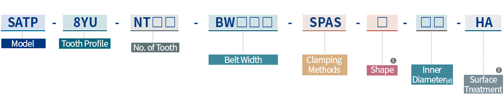
① Shape
- I
- Flange part of A.P.Lock and Taper bushing is located inside
- O
- Flange part of A.P.Lock and Taper bushing is located outside
② Surface Treatment
- HA
- Hard Anodizing
- WA
- White Anodizing