


Timing Pulley

Timing pulley is a part that transmits the rotational power
received from the timing belt to the shaft. Our products provide
sufficient tightening force without additional processing on shafts / pulleys, etc.
and support a variety of shaft fastening methods that are easy to install.
SATP-S5M Series 
High Strength Aluminum Alloy Timing Pulley 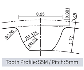 + Taper Bushing (Steel) Mounted Type
Dimensions / Performance
|
TYPE |
CAD |
NT |
P.C.D. |
O.D. |
C |
B |
ID Range (I type) |
ID Range (O type) |
||||
|
BW100 (A:11, W:16) |
BW150 (A:17, W:22) |
BW250 (A:27, W:32) |
BW100 (A:11, W:16) |
BW150 (A:17, W:22) |
BW250 (A:27, W:32) |
|||||||
|
SATP-S5M SPB |
22 |
35.01 |
34.05 |
40 |
27 |
– |
– |
– |
8 |
– |
– |
|
|
24 |
38.20 |
37.24 |
45 |
30 |
8 |
8 |
8 |
8 ~ 10 |
10 |
10 |
||
|
25 |
39.79 |
38.83 |
45 |
30 |
8 |
8 |
8 |
8 ~ 10 |
10 |
10 |
||
|
26 |
41.38 |
40.42 |
48 |
35 |
8 |
8 ~ 12 |
8 ~ 12 |
8 ~ 12 |
10 ~ 12 |
10 ~ 12 |
||
|
28 |
44.56 |
43.60 |
48 |
35 |
8 |
8 ~ 12 |
8 ~ 12 |
8 ~ 12 |
10 ~ 12 |
10 ~ 12 |
||
|
30 |
47.75 |
46.79 |
52 |
36 |
– |
10 ~ 12 |
10 ~ 12 |
10 ~ 15 |
10 ~ 15 |
10 ~ 15 |
||
|
32 |
50.93 |
49.97 |
55 |
40 |
– |
10 ~ 12 |
10 ~ 12 |
10 ~ 17 |
10 ~ 17 |
10 ~ 17 |
||
|
34 |
54.11 |
53.15 |
61 |
45 |
– |
10 ~ 12 |
10 ~ 17 |
10 ~ 17 |
10 ~ 17 |
10 ~ 17 |
||
|
36 |
57.30 |
56.34 |
61 |
45 |
– |
10 ~ 12 |
10 ~ 17 |
10 ~ 17 |
10 ~ 17 |
10 ~ 17 |
||
|
40 |
63.66 |
62.70 |
67 |
50 |
– |
10 ~ 12 |
10 ~ 17 |
10 ~ 17 |
10 ~ 17 |
10 ~ 17 |
||
|
44 |
70.03 |
69.07 |
74 |
58 |
– |
12 |
12 ~ 25 |
12 ~ 25 |
12 ~ 25 |
12 ~ 25 |
||
|
48 |
76.39 |
75.43 |
83 |
63 |
– |
12 |
12 ~ 28 |
12 ~ 28 |
12 ~ 28 |
12 ~ 28 |
||
|
50 |
79.58 |
78.62 |
87 |
67 |
– |
12 |
12 ~ 32 |
12 ~ 32 |
12 ~ 32 |
12 ~ 32 |
||
|
60 |
95.49 |
94.53 |
99 |
80 |
– |
12 |
12 ~ 35 |
12 ~ 32 |
12 ~ 35 |
12 ~ 35 |
||
|
72 |
114.59 |
113.63 |
119 |
100 |
– |
12 |
12 ~ 35 |
12 ~ 32 |
12 ~ 35 |
12 ~ 35 |
||
• Please refer to the below table for more specific available ID(d) information.
|
Available ID (d) |
8 |
10 |
11 |
12 |
14 |
15 |
16 |
17 |
18 |
19 |
20 |
22 |
24 |
25 |
28 |
30 |
32 |
35 |
|
|
Max. Permissible Torque (N·m) |
I type |
8.5 |
18 |
20 |
23 |
37 |
39 |
42 |
45 |
48 |
49 |
97 |
110 |
121 |
124 |
141 |
149 |
163 |
173 |
|
O type |
16 |
39 |
43 |
48 |
73 |
78 |
83 |
88 |
154 |
163 |
171 |
186 |
206 |
216 |
353 |
382 |
412 |
451 |
|
|
Max. Permissible Thrust Load (kN) |
I type |
2.12 |
3.59 |
3.63 |
3.76 |
5.21 |
5.1 |
5.17 |
5.23 |
5.28 |
5.12 |
9.68 |
9.98 |
10 |
9.9 |
10 |
9.89 |
10.12 |
9.88 |
|
O type |
5.34 |
5.34 |
5.34 |
5.34 |
5.34 |
5.34 |
5.34 |
5.34 |
8.74 |
8.74 |
8.74 |
8.74 |
8.74 |
8.74 |
8.74 |
8.74 |
8.74 |
8.74 |
|
|
D |
I type |
24.5 |
29 |
30 |
31 |
36 |
37 |
38 |
39 |
40 |
42 |
46 |
47 |
49 |
51 |
53 |
56 |
58 |
61 |
|
O type |
25.5 |
30 |
31 |
32 |
35 |
36 |
37 |
38 |
43 |
45 |
46 |
48 |
50 |
52 |
54 |
57 |
59 |
63 |
|
|
N |
O type |
8.5 |
10.5 |
10.5 |
10.5 |
12 |
12 |
13 |
13 |
14 |
14 |
14 |
14 |
14 |
14 |
15.5 |
15.5 |
16.5 |
16.5 |
• Keyway is NOT available for SPB series.
• Surface treatment may not be applied on inner surface of Pulley’s body.
How to Order
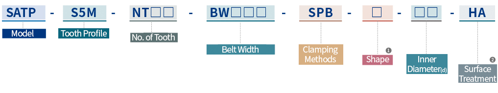
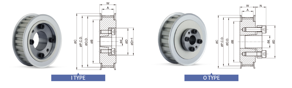
① Shape
- I
- Flange part of A.P.Lock and Taper bushing is located inside
- O
- Flange part of A.P.Lock and Taper bushing is located outside
② Surface Treatment
- HA
- Hard Anodizing
- WA
- White Anodizing