


Shaft Coupling

Coupling is a core component that transmits power and motion
from the driving shaft to the driven part while absorbing misalignment
and any possible factors that could reduce efficiency of machines
(e.g. vibration, noise, electric current, etc.)
SJC Series Go to SJC Series(Index)
Jaw Coupling 
- Product Overview
-
Dimensions / Performance / CAD
Set-Screw

Dimensions / Performance
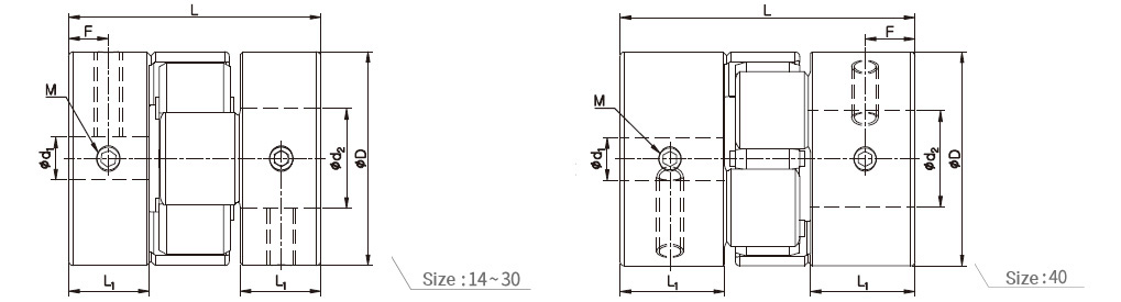
| Model | CAD | Size (±0.3mm) | Screw | Rated Torque (N·m) |
Max. Torque (N·m) |
Max. rpm (min-1) |
Moment of Inertia (kg·m2) |
Static Torsional Stiffness (N·m/rad) |
Mass (g) |
Permissible Misalignment | ||||||
|---|---|---|---|---|---|---|---|---|---|---|---|---|---|---|---|---|
| D | L | L1 | F | Size | Fastening Torque (N·m) |
Angular (˚) |
Parallel (mm) |
End-play (mm) |
||||||||
| SJC-14-BL | 14 | 22 | 7 | 3.5 | M3 | 0.7 | 2 | 4 | 27,000 | 2.1×10⁻⁷ | 22 | 6.7 | 1 | 0.05 | -0.2 ~ +0.6 | |
| SJC-14-GR | 14 | 22 | 7 | 3.5 | M3 | 0.7 | 2 | 4 | 27,000 | 2.1×10⁻⁷ | 25 | 6.7 | 1 | 0.05 | -0.2 ~ +0.6 | |
| SJC-14-RD | 14 | 22 | 7 | 3.5 | M3 | 0.7 | 2.5 | 5 | 27,000 | 2.1×10⁻⁷ | 34 | 6.7 | 1 | 0.03 | -0.2 ~ +0.6 | |
| SJC-20-BL | 20 | 30 | 10 | 4.7 | M3 | 0.7 | 4 | 8 | 19,000 | 1.0×10⁻⁶ | 50 | 18.3 | 1 | 0.07 | -0.3 ~ +0.8 | |
| SJC-20-GR | 20 | 30 | 10 | 4.7 | M3 | 0.7 | 4 | 8 | 19,000 | 1.0×10⁻⁶ | 60 | 18.3 | 1 | 0.07 | -0.3 ~ +0.8 | |
| SJC-20-RD | 20 | 30 | 10 | 4.7 | M3 | 0.7 | 6 | 12 | 19,000 | 1.0×10⁻⁶ | 74 | 18.3 | 1 | 0.05 | -0.3 ~ +0.8 | |
| SJC-25-BL | 25 | 31.3 | 10 | 5 | M4 | 1.7 | 9 | 18 | 15,000 | 2.7×10⁻⁶ | 220 | 30 | 1 | 0.07 | -0.4 ~ +1.0 | |
| SJC-25-GR | 25 | 31.3 | 10 | 5 | M4 | 1.7 | 9 | 18 | 15,000 | 2.7×10⁻⁶ | 260 | 30 | 1 | 0.07 | -0.4 ~ +1.0 | |
| SJC-25-RD | 25 | 31.3 | 10 | 5 | M4 | 1.7 | 12 | 24 | 15,000 | 2.7×10⁻⁶ | 300 | 30 | 1 | 0.05 | -0.4 ~ +1.0 | |
| SJCA-30-BL | 30 | 35.3 | 11.3 | 5.6 | M4 | 1.7 | 12 | 24 | 13,000 | 6.2×10⁻⁶ | 170 | 46 | 1 | 0.08 | -0.4 ~ +1.0 | |
| SJCA-30-GR | 30 | 35.3 | 11.3 | 5.6 | M4 | 1.7 | 12 | 24 | 13,000 | 6.2×10⁻⁶ | 200 | 46 | 1 | 0.08 | -0.4 ~ +1.0 | |
| SJCA-30-RD | 30 | 35.3 | 11.3 | 5.6 | M4 | 1.7 | 16 | 32 | 13,000 | 6.2×10⁻⁶ | 220 | 46 | 1 | 0.06 | -0.4 ~ +1.0 | |
| SJCB-30-BL | 30 | 44.7 | 16 | 7.3 | M4 | 1.7 | 12 | 24 | 13,000 | 8.2×10⁻⁶ | 170 | 60 | 1 | 0.08 | -0.4 ~ +1.0 | |
| SJCB-30-GR | 30 | 44.7 | 16 | 7.3 | M4 | 1.7 | 12 | 24 | 13,000 | 8.2×10⁻⁶ | 200 | 60 | 1 | 0.08 | -0.4 ~ +1.0 | |
| SJCB-30-RD | 30 | 44.7 | 16 | 7.3 | M4 | 1.7 | 16 | 32 | 13,000 | 8.2×10⁻⁶ | 220 | 60 | 1 | 0.06 | -0.4 ~ +1.0 | |
| SJCA-40-BL | 40 | 55 | 19.5 | 9.3 | M5 | 4 | 17 | 34 | 9,600 | 3.3×10⁻⁵ | 1,500 | 132 | 1 | 0.06 | -0.5 ~ +1.2 | |
| SJCA-40-GR | 40 | 55 | 19.5 | 9.3 | M5 | 4 | 17 | 34 | 9,600 | 3.3×10⁻⁵ | 1,600 | 132 | 1 | 0.06 | -0.5 ~ +1.2 | |
| SJCA-40-RD | 40 | 55 | 19.5 | 9.3 | M5 | 4 | 21 | 42 | 9,600 | 3.3×10⁻⁵ | 1,750 | 132 | 1 | 0.04 | -0.5 ~ +1.2 | |
| SJCB-40-BL | 40 | 66 | 25 | 11.6 | M5 | 4 | 17 | 34 | 9,600 | 4.0×10⁻⁵ | 1,500 | 163 | 1 | 0.06 | -0.5 ~ +1.2 | |
| SJCB-40-GR | 40 | 66 | 25 | 11.6 | M5 | 4 | 17 | 34 | 9,600 | 4.0×10⁻⁵ | 1,600 | 163 | 1 | 0.06 | -0.5 ~ +1.2 | |
| SJCB-40-RD | 40 | 66 | 25 | 11.6 | M5 | 4 | 21 | 42 | 9,600 | 4.0×10⁻⁵ | 1,750 | 163 | 1 | 0.07 | -0.5 ~ +1.2 | |
- The Moment of Inertia and Mass values are based on products with max. Inner diameter.
- Please modify rated/max. torque value with temperature correction factor when it’s higher than 30ºC.
- Max. torque/rated torque is the value regarding to a coupling’s self-durability and is not related to slip-torque between the coupling bore and the shaft. (Set-screw type is usually less durable than other clamping method, thus please consider it has a complementary option e.g. keyway along with.)
Standard Inner Diameter (ID)
| Model | Standard Inner Diameter (d1, d2) (mm) | ||||||||||||||||
|---|---|---|---|---|---|---|---|---|---|---|---|---|---|---|---|---|---|
| 3 | 4 | 4.5 | 5 | 6 | 6.35 | 7 | 8 | 9 | 9.525 | 10 | 11 | 12 | 14 | 15 | 16 | 18 | |
| SJC□-14 | ● | ● | ● | ● | |||||||||||||
| SJC□-20 | ● | ● | ● | ● | ● | ● | ● | ||||||||||
| SJC□-25 | ● | ● | ● | ● | ● | ● | ● | ● | |||||||||
| SJC□-30 | ● | ● | ● | ● | ● | ● | ● | ● | ● | ● | |||||||
| SJC□-40 | ● | ● | ● | ● | ● | ● | ● | ● | ● | ● | |||||||
- The recommended shaft tolerance is h7.
- Custom process (e.g. non-standard Inner diameter, special tolerance etc.) is also available upon a special request in prior to order placement.
- Keyway is available. (Optional)
Set-Screw

Dimensions / Performance
| Model | CAD | Size (±0.3mm) | Screw | Rated Torque (N·m) |
Max. Torque (N·m) |
Max. rpm (min-1) |
Moment of Inertia (kg·m2) |
Static Torsional Stiffness (N·m/rad) |
Mass (g) |
Permissible Misalignment | ||||||
|---|---|---|---|---|---|---|---|---|---|---|---|---|---|---|---|---|
| D | L | L1 | F | Size | Fastening Torque (N·m) |
Angular (˚) |
Parallel (mm) |
End-play (mm) |
||||||||
| SJC-55-BL | 55 | 78.3 | 30.3 | 14 | M6 | 7 | 60 | 120 | 7,500 | 1.7×10⁻⁴ | 3,000 | 344 | 1 | 0.09 | -0.5 ~ +1.4 | |
| SJC-55-DG | 55 | 78.3 | 30.3 | 14 | M6 | 7 | 60 | 120 | 7,500 | 1.7×10⁻⁴ | 4,500 | 344 | 1 | 0.08 | -0.5 ~ +1.4 | |
| SJC-55-GR | 55 | 78.3 | 30.3 | 14 | M6 | 7 | 60 | 120 | 7,500 | 1.7×10⁻⁴ | 4,500 | 344 | 1 | 0.09 | -0.5 ~ +1.4 | |
| SJC-55-RD | 55 | 78.3 | 30.3 | 14 | M6 | 7 | 75 | 150 | 7,500 | 1.7×10⁻⁴ | 6,000 | 344 | 1 | 0.06 | -0.5 ~ +1.4 | |
| SJC-65-BL | 65 | 90.3 | 35.3 | 17.2 | M8 | 15 | 150 | 300 | 6,000 | 3.9×10⁻⁴ | 6,500 | 535 | 1 | 0.1 | -0.6 ~ +1.5 | |
| SJC-65-DG | 65 | 90.3 | 35.3 | 17.2 | M8 | 15 | 150 | 300 | 6,000 | 3.9×10⁻⁴ | 8,500 | 535 | 1 | 0.09 | -0.6 ~ +1.5 | |
| SJC-65-GR | 65 | 90.3 | 35.3 | 17.2 | M8 | 15 | 150 | 300 | 6,000 | 3.9×10⁻⁴ | 8,500 | 535 | 1 | 0.1 | -0.6 ~ +1.5 | |
| SJC-65-RD | 65 | 90.3 | 35.3 | 17.2 | M8 | 15 | 180 | 360 | 6,000 | 3.9×10⁻⁴ | 10,000 | 535 | 1 | 0.08 | -0.6 ~ +1.5 | |
| SJC-80-BL | 80 | 114.2 | 45.2 | 21.7 | M8 | 15 | 300 | 600 | 5,000 | 1.1×10⁻³ | 8,000 | 1,150 | 1 | 0.1 | -0.6 ~ +1.5 | |
| SJC-80-DG | 80 | 114.2 | 45.2 | 21.7 | M8 | 15 | 300 | 600 | 5,000 | 1.1×10⁻³ | 12,000 | 1,150 | 1 | 0.09 | -0.6 ~ +1.5 | |
| SJC-80-GR | 80 | 114.2 | 45.2 | 21.7 | M8 | 15 | 300 | 600 | 5,000 | 1.1×10⁻³ | 12,000 | 1,150 | 1 | 0.1 | -0.6 ~ +1.5 | |
| SJC-80-RD | 80 | 114.2 | 45.2 | 21.7 | M8 | 15 | 380 | 760 | 5,000 | 1.1×10⁻³ | 14,000 | 1,150 | 1 | 0.08 | -0.6 ~ +1.5 | |
| SJC-100-BL | 104 | 140.2 | 56.2 | 27.3 | M10 | 25 | 500 | 1,000 | 4,000 | 4.8×10⁻³ | 24,000 | 2,650 | 1 | 0.15 | -0.6 ~ +2.0 | |
| SJC-100-DG | 104 | 140.2 | 56.2 | 27.3 | M10 | 25 | 500 | 1,000 | 4,000 | 4.8×10⁻³ | 24,000 | 2,650 | 1 | 0.12 | -0.6 ~ +2.0 | |
| SJC-100-GR | 104 | 140.2 | 56.2 | 27.3 | M10 | 25 | 500 | 1,000 | 4,000 | 4.8×10⁻³ | 30,000 | 2,650 | 1 | 0.15 | -0.6 ~ +2.0 | |
| SJC-100-RD | 104 | 140.2 | 56.2 | 27.3 | M10 | 25 | 600 | 1,200 | 4,000 | 4.8×10⁻³ | 40,000 | 2,650 | 1 | 0.1 | -0.6 ~ +2.0 | |
- The Moment of Inertia and Mass values are based on products with max. Inner diameter.
- Please modify rated/max. torque value with temperature correction factor when it’s higher than 30ºC.
- Max. torque/rated torque is the value regarding to a coupling’s self-durability and is not related to slip-torque between the coupling bore and the shaft. (Set-screw type is usually less durable than other clamping method, thus please consider it has a complementary option e.g. keyway along with.)
Standard Inner Diameter (ID)
| Model | Standard Inner Diameter (d1, d2) (mm) | ||||||||||||||||||
|---|---|---|---|---|---|---|---|---|---|---|---|---|---|---|---|---|---|---|---|
| 12 | 14 | 15 | 16 | 18 | 19 | 20 | 22 | 24 | 25 | 26 | 28 | 30 | 32 | 35 | 40 | 45 | 50 | 60 | |
| SJC-55 | ● | ● | ● | ● | ● | ● | ● | ● | ● | ● | ● | ● | |||||||
| SJC-65 | ● | ● | ● | ● | ● | ● | ● | ● | ● | ● | ● | ● | ● | ||||||
| SJC-80 | ● | ● | ● | ● | ● | ● | ● | ● | ● | ● | ● | ● | ● | ● | ● | ||||
| SJC-100 | ● | ● | ● | ● | ● | ● | ● | ● | ● | ● | ● | ● | ● | ||||||
- The recommended shaft tolerance is h7.
- Custom process (e.g. non-standard Inner diameter, special tolerance etc.) is also available upon a special request in prior to order placement.
- Keyway is available. (Optional)